SEAWORKS (Vanuatu), Main Street, Nambatu, P.O. Box 3242 Port Vila – Phone +678 7100 230 (WhatsApp)
SEAWORKS (New Caledonia), BP 7036 – 98801 Noumea Cedex – Phone +687 87 55 05
We operate throughout Oceania Islands, with the capacity to stay working at remote locations
* Sorry, but we only supply commercial, government or social entity with this equipment (not any individual).
On this page (from Table of contents) :
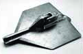
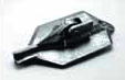
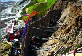
Manta Ray and Stingray earth anchors are driven tipping plate soil anchors dependant on soil strength for reaction of tensile loads.
Manta Ray anchors have working loads up to 20 kips, and Stingray anchors have working loads up to 50 kips.
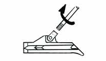
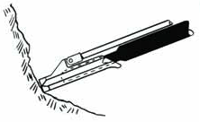
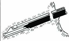
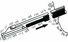
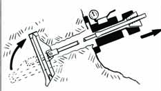
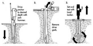
After driving the anchor to the required depth, the driving tool (called drive steel) is removed. The anchor is then tipped and proof tested with an Anchor Locking Kit from its edgewise-driving position to present its bearing area to the soil. This is called “load locking” and provides an immediate proof test of each anchor.
Manta Ray and Stingray anchors offer many significant advantages:
• Fast, easy installation
• Immediate proof test results
• No grout
• Inexpensive installation equipment
• Environmentally friendly
• No drilling required
• Superior Holding Capacity
• Anchors for a wide range of soils & applications
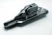
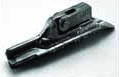
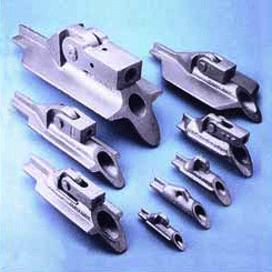
There are eight (8) Manta Ray Anchors and three (3) Stingray Anchors with light to heavy duty holding capacities.
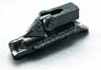
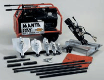
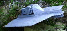
Shown above are six different Manta Ray anchor heads. All anchors are made of galvanized ductile iron, can be driven with the drive steel set (except the MR-88 & M-68) and can be tested to the desired holding capacity with the load locker.
The anchors are designed to utilize solid steel rods as load carrying members. Bars and accessories for Manta Ray and Sting Ray anchors can be found on the following pages.


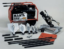
Drive Steel :
Load Locking Kits :

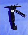
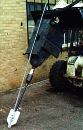
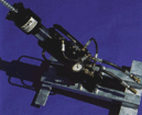
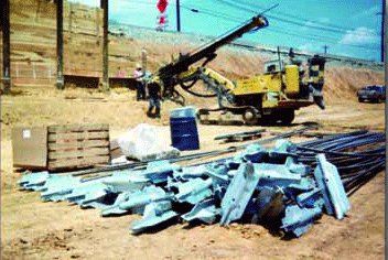
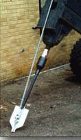
Boom mounted demolitions or compactions are very effective for driving Manta Ray and Stingray anchors. This method requires a special tool in the breaker or a socket welded to the bottom of the compactor to hold the drive steel. Skid steer loaders, backhoes or excavators work well. 4,000 to 16,000 lb. vehicles with 250 to 500 foot-pound pavement breakers are best for Manta Rays, and 16,000 to 30,000 lb. vehicles with 500 to 1,000 foot-pound pavement breakers are best for Stingrays. Breaker tools and vibro sockets are available upon request.
Rock Drills :
Manual Installation :
In some applications, Manta Ray anchors are driven into the soil with a 90 lb. pavement breaker and coupled drive steel.
Pneumatic or hydraulic breakers are acceptable, but a 90 lb. weight class breaker is necessary.
Manual installation of Stingray anchors is not recommended.
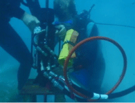
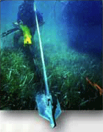
From the Great Barrier Reef to the Red Sea, Manta Rays are used to anchor moorings that help protect coral reefs and other natural resources. Now there is an environmentally friendly anchor system that installs easily underwater with conventional equipment for buoys, floating docks, man made reefs and more.
Moorings are used primarily to protect vulnerable sea floor structures and as a secondary benefit they make mooring visiting boats easier.
Through the world, the positioning of moorings is determined by the need to protect sea floor structures of biological and ecological importance.
MANTA RAYs are driven into the ground, not augured or torqued, nor is a hole dug or drilled.
There is “no disturbance” or “displacement” of soil.
Unlike other anchoring systems, MANTA RAY actually compacts the soil around itself : a clean, safe and simple operation.
The mooring system chosen uses various embedment mooring technologies proven by specialists John and Judy Halas of Environmental Moorings International, Florida.
The equipment used depends on the bottom composition : in sand areas “MANTA RAY” anchors are used, while in granite and limestone areas stainless steel pins are preferred which are secured either by marine cement or by epoxy cement.
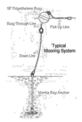
Each mooring is designed for the particular site where it is to be installed and typically consists of the following components : an anchor unit or anchor pin ; a heavy duty mooring line, with a float attached a metre or so from the anchor point to keep the line off the sea bed ; a surface buoy on a looped bridle, to make it easy to maintain ; a floating pick-up line for boats to tie up to.
Manta Ray and Stingray earth anchors are driven tipping plate soil anchors dependant on soil strenght for reaction of tensile loads. Manta Ray anchors have working loads up to 20 kips, and Stingray anchors have working loads up to 50 kips. After driving the anchor to the required depth, the driving tool (called drive steel) is removed. The anchor is then tipped and proof tested with Williams Anchor Locking Kit from its edgewise-driving position to present its bearing area to the soil. This is called “load locking” and provides an immediate proof test of each anchor.
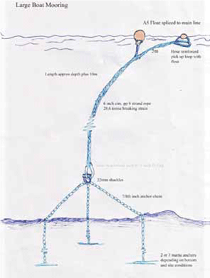
Then small boat moorings can utilise a single anchor, large boat moorings can utilise three anchors shackled to a 1-inch D-ring.
A number of considerations have to be taken into account for the site selection : sites that would specifically protect reefs, sites close to popular dive sites and sites that would allow for convenient mooring for boats visiting the terrestrial destinations.
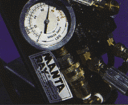
For Manta Ray, the LL-1 is a 10-ton fast acting jack with an 8 inch stroke.
The direct reading gauge and rod gripping jaws make load locking easy and quick.

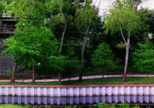
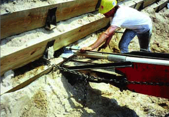
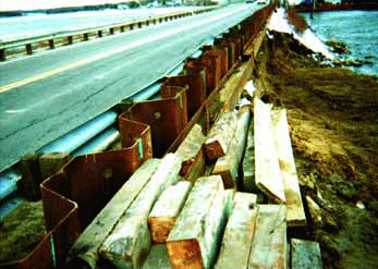
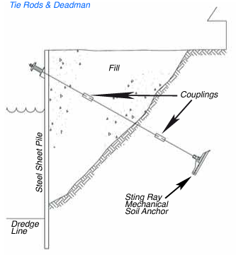
The anchoring of seawalls with Manta Ray Anchors eliminates expensive and complicated tie-back methods. Minimal, if any, excavation is required. Using Manta Ray Anchors results in aesthetically pleasing and cost-effective seawall installations.
| Anchor |
Structural Safety Factor 2:1 |
Recommended Anchor Rod |
Weight per Each |
|
|---|---|---|---|---|
| Diameter * |
Part Number |
|||
| Manta Ray | ||||
| MR-68 |
2.5 kips (11 kN) |
3/8" (10 mm) |
B8S-03 |
1 lbs. (0.45 kg) |
| MR-88 |
5 kips (22 kN) |
1/2" (12 mm) |
B8S-04 |
2.2 lbs. (1 kg) |
| MR-4 |
8.5 kips (36 kN) |
#6 - 3/4" (20 mm) |
R61-06 |
4.7 lbs. (2.1 kg) |
| MR-3 |
10 kips (45 kN) |
#6 - 3/4" (20 mm) |
R61-06 |
6 lbs. (2.7 kg) |
| MR-2 |
20 kips (89 kN) |
#6 - 3/4" (20 mm) |
R61-06 |
10 lbs. (4.5 kg) |
| MR-1 |
20 kips (89 kN) |
#6 - 3/4" (20 mm) |
R61-06 |
12 lbs. (5.4 kg) |
| MR-SR |
20 kips (89 kN) |
#6 - 3/4" (20 mm) |
R61-06 |
21 lbs. (9.5 kg) |
| MK-B |
20 kips (89 kN) |
#6 - 3/4" (20 mm) |
R61-06 |
85 lbs. (38.5 kg) |
| Sting Ray | S.F. | Diameter * | Part Number | Weight |
| SR-1 |
45.5 kips (198 kN) |
#9 - 1-1/8" (28 mm) |
R61-09 |
47 lbs. (21.3 kg) |
| SR-2 |
50 kips (223 kN) |
#9 - 1-1/8" (28 mm) |
R61-09 |
66 lbs. (30 kg) |
| SR-3 |
50 kips (223 kN) |
#9 - 1-1/8" (28 mm) |
R61-09 |
91 lbs. (41.2 kg) |
Anchor Rods are fully threaded and can be field cut and coupled.
* Anchor rod lengths: R61-06 & R61-09 -
Up to 50 feet uncoated
B8S-03 & B8S-04 - Up to 20 feet
Recommended: Galvanized rods should be cut to size prior to galvanizing to insure good nut fit.
|
Common Soil Type Description |
Typical Blow Count “N” per ASTM-D 1586 |
MR-68 | MR-88 | MR-4 | MR-3 | MR-2 | MR-1 | MR-SR | MK-B |
|---|---|---|---|---|---|---|---|---|---|
| Peat, organic silts; inundates silts fly ash | 0 - 5 | N.A. | 0.2-0.9 kips (0.9-4 kN) (4, 6) |
0.3-1.5 kips (1.3-7 kN) (4, 6) |
0.8-3 kips (3.5-13 kN) (4, 6) |
2-5 kips (9-22 kN) (4, 6) |
3-8 kips (13-37 kN) (4, 6) |
4-12 kips (18-53 kN) (4, 6) |
6-16 kips (27-71 kN) (4, 6) |
| Loose fine sand; alluvium; soft-firm clays; varied clays; fills | 4 - 8 | 0.4-0.8 kips (1.8-3.5 kN) (4, 6) |
0.9-1.5 kips (4-7 kN) (4, 6) |
1.5-2.5 kips (7-11 kN) (4, 6) |
3-5 kips (13-22 kN) (4, 6) |
5-8 kips (22-36 kN) (4, 6) |
8-12 kips (36-53 kN) (4, 6) |
9-14 kips (40-62 kN) (4, 6) |
13-20 kips (58-89 kN) (4, 6) |
| Loose to medium dense fine to coarse sand; firm to stiff clays and silts | 7 - 14 | 0.75-1.3 kips (3.5-6 kN) (4) |
1.5-2.5 kips (7-11 kN) (4) |
2.5-4 kips (11-18 kN) (4) |
5-8 kips (22-36 kN) (4) |
7-10 kips (31-44 kN) (4) |
10-15 kips (44-67 kN) (4) |
14-18 kips (62-80 kN) (4) |
20 kips (89 kN) (4) |
| Medium dense coarse sand and sandy gravel; stiff to very stiff silts and clays | 14 - 25 | 1-1.5 kips (5-7 kN) (4) |
2-3 kips (9-13 kN) (4) |
3.5-4.5 kips (16-20 kN) (4) |
7-9 kips (31-40 kN) (4) |
9-12 kips (40-53 kN) (4) |
15-20 kips (67-89 kN) (4) |
18-20 kips (80-89 kN) (4) |
20 kips (89 kN) (2, 4) |
| Medium dense sandy gravel; very stiff to hard silts and clays | 24 - 40 | 1.5-2 kips (7-9 kN) (4) |
3-4 kips (13-18 kN) (4) |
4.5-6 kips (20-25 kN) (4) |
9-10 kips (40-45 kN) (4) |
12-18 kips (53-80 kN) (4) |
18-20 kips (80-89 kN) (2, 4) |
20 kips (89 kN) (2, 4) |
20 kips (89 kN) (2, 3, 4) |
| Dense clays, sands and gravel; hard silts and clays | 35 - 50 | 2-2.5 kips (9-11 kN) (4) |
4-5 kips (18-22 kN) (4) |
6-8.5 kips (27-36 kN) (4) |
10 kips (45 kN) (2, 4) |
15-20 kips (67-89 kN) (2, 4) |
20 kips (89 kN) (2, 4) |
20 kips (89 kN) (2, 3, 4) |
20 kips (89 kN) (1, 3) |
| Dense fine sand; very hard silts and clays | 45 - 60 | 2.5 kips (11 kN) (2, 3, 4) |
5 kips (22 kN) (2, 3, 4) |
8.5 kips (36 kN) (2, 3, 4) |
10 kips (45 kN) (2, 3, 4) |
20 kips (89 kN) (2, 4) |
20 kips (89 kN) (1, 3, 4) |
20 kips (89 kN) (1, 3) |
20 kips (89 kN) (1, 3, 5) |
| Very dense and / or cemented sands; coarse gravel and cobbles | 60 - 100+ | 2.5 kips (11 kN) (1, 3) |
5 kips (22 kN) (1, 3) |
8.5 kips (36 kN) (1, 3) |
10 kips (45 kN) (1, 3) |
20 kips (89 kN) (1, 3, 4) |
20 kips (89 kN) (1, 3) |
20 kips (89 kN) (1, 3, 5) |
1 - Drilled hole required to install.
2 - Installation may be difficult. Pilot hole may be required.
3 - Holding capacity limited by working load of anchors.
4 - Holding capacity limited by soil failure.
5 - Not recommended in these soils.
6 - Wide variation in soil properties reduces prediction accuracy.
A minimum of 2:1 Safety Factor is recommended.
Use this chart for estimation only, true capacity must be tested with anchor locker.
The values in chart are based on minimum 3' embedment depth for models MR-68 & MR-88 and 7' for Models MR4 thru MK-B. (Minimum overburden depth is 4'.) Field testing is recommended for other possible depths.
|
Common Soil Type Description |
Typical Blow Count “N” per ASTM-D 1586 |
SR-1 | SR-2 | SR-3 |
|---|---|---|---|---|
| Peat, organic silts; inundates silts fly ash | 0 - 5 | N.A. | N.A. | N.A. |
| Loose fine sand; alluvium; soft-firm clays; varied clays; fills | 4 - 8 |
13-19 kips (58-82 kN) (4, 6) |
19-28 kips (85-125 kN) (4, 6) |
24-37 kips (107-165 kN) (4, 6) |
| Loose to medium dense fine to coarse sand; firm to stiff clays and silts | 7 - 14 |
16-24 kips (72-107 kN) (4) |
27-36 kips (120-160 kN) (4) |
37-48 kips (165-214 kN) (4) |
| Medium dense coarse sand and sandy gravel; stiff to very stiff silts and clays | 14 - 25 |
24-32 kips (107-142 kN) (4) |
31-48 kips (138-214 kN) (4) |
48-50 kips (214-223 kN) (4) |
| Medium dense sandy gravel; very stiff to hard silts and clays | 24 - 40 |
29-41 kips (129-182 kN) (4) |
46-50 kips (205-223 kN) (4) |
50 kips (223 kN) (4) |
| Dense clays, sands and gravel; hard silts and clays | 35 - 50 |
39-45.5 kips (173-198 kN) (4) |
50 kips (223 kN) (2, 4) |
50 kips (223 kN) (2, 3, 4) |
| Dense fine sand; very hard silts and clays | 45 - 60 |
45.5 kips (198 kN) (2, 4) |
50 kips (223 kN) (2, 4) |
50 kips (223 kN) (2, 3) |
| Very dense and / or cemented sands; coarse gravel and cobbles | 60 - 100+ |
45.5 kips (198 kN) (1, 3) |
50 kips (223 kN) (1, 3) |
50 kips (223 kN) (1, 3, 5) |
1 - Drilled hole required to install.
2 - Installation may be difficult. Pilot hole may be required.
3 - Holding capacity limited by working load of anchors.
4 - Holding capacity limited by soil failure.
5 - Not recommended in these soils.
6 - Wide variation in soil properties reduces prediction accuracy.
A minimum of 2:1 Safety Factor is recommended.
Use this chart for estimation only, true capacity must be tested with anchor locker.
The values in chart are based on minimum 3' embedment depth for models MR-68 & MR-88 and 7' for Models MR4 thru MK-B. (Minimum overburden depth is 4'.) Field testing is recommended for other possible depths.
|
Bar Desig. & Nominal Dia. |
Minimum Net Area Thru Threads |
Minimum Ultimate Strength |
Minimum Yield Strength |
Nominal Weight |
Approx. Thread Major Dia. |
Part Number |
|---|---|---|---|---|---|---|
|
#6 - 3/4" (20 mm) |
0.44 in2 (284 mm2) |
44 kips (196 kN) |
33 kips (147 kN) |
1.5 lbs./ft. (2.36 Kg/M) |
7/8" (22.2 mm) |
R61-06 |
|
#9 - 1-1/8" (28 mm) |
1.00 in2 (645 mm2) |
100 kips (445 kN) |
75 kips (334 kN) |
3.4 lbs./ft. (5.06 Kg/M) |
1-1/4" (31.8 mm) |
R61-09 |
|
Bar Diameter |
Approx. Thread Major Dia. |
Minimum Yield Strength |
Minimum Ultimate Strength |
Minimum Net Area Thru Threads |
Part Number |
|---|---|---|---|---|---|
|
1/2" - 13 UNC (12 mm) |
0.142 in2 (91 mm2) |
13 kips (57.8 kN) |
18 kips (80.1 kN) |
1/2" (13 mm) |
B8S-04 |
| Nominal Bar Diameter |
Outside Diameter |
Overall Length |
Part Number |
|---|---|---|---|
| #6 - 3/4" (20 mm) |
1-1/4" (31.8 mm) |
3-1/2" (88.9 mm) |
R62-06 |
| #9 - 1-1/8" (28 mm) |
1-7/8" (47.7 mm) |
5" (127 mm) |
R62-09 |
| Nominal Bar Diameter |
Across Flats |
Across Corners |
Thickness | Part Number |
|---|---|---|---|---|
| #6 - 3/4" (20 mm) |
1-1/4" (31.8 mm) |
1.44" (36.7 mm) |
1-5/8" (41.4 mm) |
R63-06 |
| #9 - 1-1/8" (28 mm) |
1-7/8" (47.8 mm) |
2.17" (55.0 mm) |
2" (55.5 mm) |
R63-09 |
| Nominal Bar Diameter |
Outside Diameter |
Inside Diamter |
Thickness | Part Number |
|---|---|---|---|---|
| #6 - 3/4" (20 mm) |
1-3/4" (45 mm) |
15/16" (24 mm) |
5/32" (3.4 mm) |
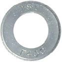
R9F-07-436 |
| #9 - 1-1/8" (28 mm) |
2-1/4" (57 mm) |
1-1/4" (32 mm) |
5/32" (4.0 mm) |
R9F-09-436 |
| Nominal Bar Diameter |
Thickness | Outside Dome |
Part Number |
|---|---|---|---|
| #6 - 3/4" (20 mm) |
35/64" (13.9 mm) |
2" (51 mm) |
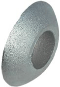
R81-0675 |
| #9 - 1-1/8" (28 mm) |
3/4" (19.1 mm) |
2-3/4" (70 mm) |
R81-0975 |
|
Nominal Bar Diameter |
Degree of Bevel |
Outside Diameter |
Inside Diamter |
Maximum Thickness |
Minimum Thickness |
Part Number |
|---|---|---|---|---|---|---|
|
#6 - 3/4" (20 mm) |
9° |
2" sq. (50.8 mm) |
1" (25.4 mm) |
17/32" (13.5 mm) |
15/64" (6.1 mm) |
R8M-07 |
|
#9 - 1-1/8" (28 mm) |
15° |
2-13/16" (71.4 mm) |
1-5/16" (33.3 mm) |
1" (25 mm) |
5/16" (7.9 mm) |
R8M-09S |
These steel bearing plates are standard with a round hole for non-grouted anchors.
Also available are dished plates for use with spherical hex nuts and keyhole plates which provide free access for grout tube entry.
Bearing plates are customized for each application.
Plate dimensions should be specified around the parameters of the project.
In addition, corrosion protection should be considered along with specifying hole diameter and bar angle.
Stainless steel plates available upon request.
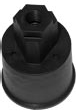
These end caps, produced from fiber reinforced nylon, steel or PVC to provide corrosion protection at otherwise exposed anchor ends.
Most often the caps are packed with corrosion inhibiting wax or grease.
Caps made from reinforced nylon and steel are used in exposed impact areas.
These end caps, produced from fiber reinforced nylon, steel or PVC to provide corrosion protection at otherwise exposed anchor ends.
Most often the caps are packed with corrosion inhibiting wax or grease.
Caps made from reinforced nylon and steel are used in exposed impact areas.
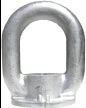
| Eye Nut Designation |
Inside Width |
Inside Height |
Ring Diameter |
Overall Height |
Taps Available |
Straight Tension Ultimate Strength |
Blank Part Number |
|---|---|---|---|---|---|---|---|
|
NEB 1 Ductile Iron |
2" (51 mm) |
2" (51 mm) |
1-1/8" (29 mm) |
5-1/8" (130 mm) |
3/4"; 7/8"; 1"* (20; 22; 25 mm) |
35 kips (156 kN) |
E1M-00-001 |
|
NEB 50 Ductile Iron |
3" (76 mm) |
3' (76 mm) |
1" (25 mm) |
5-3/4" (146 mm) |
1/2"; 3/4" (13; 20 mm) |
26 kips (116 kN) |
E1M-00-050 |
|
NEB 75R Ductile Iron |
4" (102 mm) |
5" (127 mm) |
1" (25 mm) |
7-3/4" (197 mm) |
1/2"; 3/4" (13; 20 mm) |
23 kips (102 kN) |
E1M-00-75R |
|
NEB 100 Ductile Iron |
4" (102 mm) |
4-1/2" (114 mm) |
1-1/4' (32 mm) |
8" (203 mm) |
1"; 1-1/4"; 1-3/8"* (25; 32; 35 mm) |
65 kips (289 kN) |
E1M-00-100 |
|
NEB 200 Ductile Iron |
5" (127 mm) |
6" (152 mm) |
2" (51 mm) |
11" (274 mm) |
1-3/8"; 2" (35; 51 mm) |
150 kips (667 kN) |
E1M-00-200 |
|
E1N Malleable |
2" (51 mm) |
2-1/2" (64 mm) |
7/8" (22 mm) |
5-1/8" (130 mm) |
Grade 75 #6, #7, #8 |
35 kips (156 kN) |
E1M-00-E1N |
|
CCF 1 CCF 2 CCF 3 CCF 4 Steel |
up to 4" (102 mm) |
up to 6-1/4" (159 mm) |
up to 1-1/2" (38 mm) |
up to 8-1/2" (216 mm) |
Grade 75 #6 through #18 |
up to 260 kips (1157 kN) |
E1M-00-CCF1 E1M-00-CCF2 E1M-00-CCF3 E1M-00-CCF4 |
| * 150 KSI All-Thread-Bar may not be used in 1" diameter for the NEB 1 or in 1-3/8" diameter for the NEB 100. | |||||||
Should you require any further assistance or information, please do not hesitate to contact us
We can install these anchoring systems through the Pacific, or provide you with the necessary equipment for the installation.